
Report to the Cabal: Part 2
The research I did in support of the Moebius Models 1/72 SKIPJACK kit resulted in a rather thick folder of plans (both BUSHIP based and private sources), photographs, tables, and news clippings.
Pull up a chair, boy’s and girl’s, it’s Story Time with Uncle Dave:
In the early ’70’s while working as an exhibit maker (and toilet-scrubber) at the Submarine Force Library and Museum, I was tasked with bagging for ‘burn’, filing cabinets full of American submarine plans, the Booklet of General Plans and Docking and plans dating back to the A-Class boats (up to and including the GUPPY converted TENCH class boats.) Those hard copies, blue-prints if you will, were being replaced by micro-film captures of the documents, and the museum wanted our old, bulky, dusty prints out of the way. It was all unclassified. Hmmmm …. what to do?
As if by magic, most of that trash wound up at my home. Unknown to me, at a different location on the upper base, some of the general arrangement post war diesel and older nuclear submarine plans had also been declassified and scheduled for disposal. Enter Jim Christly, fellow model builder, canvas artist, historian and well-known author. Jim also worked at the upper base and in his travels found where those plans were and – knowing my keen interest in all things SKIPJACK – one day stopped by my workshop/dungeon and tossed a set of downgraded SKIPJACK documents in my lap. Wow!
Many years later Greg Sharpe (one of the finest R/C model submarine fabricators on the planet) had set up a business producing and selling builder’s plans of modern submarines. He had always been very helpful with my various researches, so I reciprocated and shared with him the SKIPJACK file which contained good quality copies of the BUSHIP drawings. Eventually, Greg produced an excellent, well formatted set of drawings.
Long story short: Greg’s drawings were the backbone of the package sent to China to get the SKIPJACK kit tooling made. Accompanying the research package was a completed and well detailed 1/96 scale SKIPJACK model intended for scanning as the basis to generate a CAD file.
After Moebius committed to the project of producing a 1/72 SKIPJACK kit, I took on the assignment of lead-man. My job being to gather and send off to Dave Metzner, the Moebius product development guy, a package containing all the information the Chinese needed to render an accurate kit.
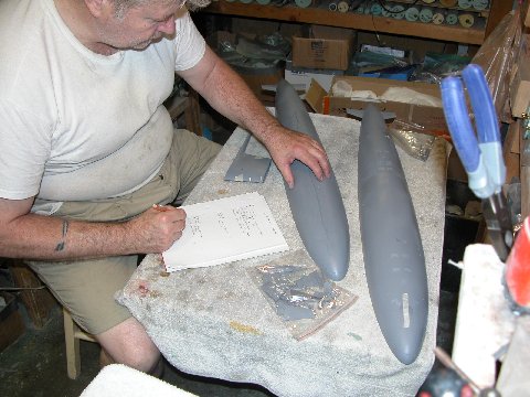
Checking the 3D printed mockup
I’m pictured here surveying the mockup they sent. That mockup, 3D printed in accordance to the materials I sent them, had major problems! That list you see me compiling grew to an eventual three pages of things that had to be fixed.
One of the many faults found on the mockup identified here: incorrect location of the transitioning fillet between the diesel exhaust fairing and the sail sides.
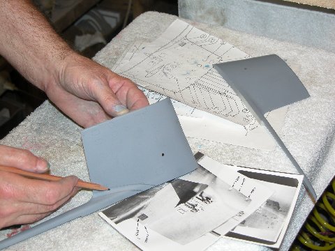
Sail review work
Like all other anomalies found on the mockup, I performed a re-contouring action to get the mockup parts as close to documentation as I could. Note the pictures of a SKIPJACK sail under the work – sometimes photos are the only way to go when the plans are not enough. Such was case here: The plans showed only the plan and profile of the fairing-sail interface, but no indication as to the radius and sweep of the fillet between the two structures. This is when you make use of your well trained eyes and good old ‘computer number-one’.
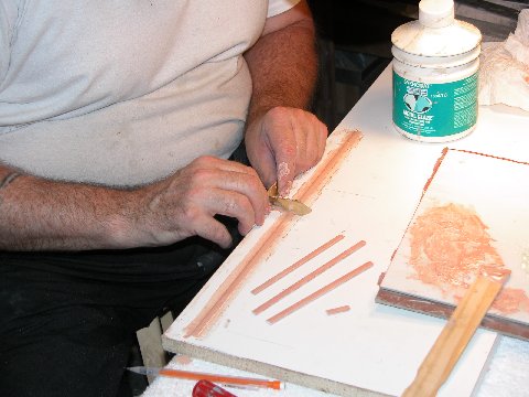
Screed technique for forming half mast master parts
In parallel with mockup correction I set about the task of working up masters to enhance the look and function of the many retractable masts that fit within the SKIPJACK’s sail. The proposed kit parts had masts long enough to project atop the sail in their ‘raised’ positions, but only had enough material in the bases to fit sockets in the top of the sail. Not suitable for a practical retraction/extension mechanism. To address this, first a linear screeding tool was used to form half-mast masters from a two-part automotive filler. The brass screeding blade between my hands has a fence that rests on the outer edge of this molding-board, I lay down some catalyzed filler on the board, under the opening cut into the blade of the screeding tool – that opening representing 1/2 of the desired mast section. As I pull the blade lengthwise across the mold board, the opening in the blade forces the filler to adopt the shape of the half-mast. The mold board was precoated with mold-release wax to aid a clean break-away of the half-mast master off the mold-board after the work was done. The master was broken into two equal length pieces, and glued together, face-to-face, making a complete mast master.
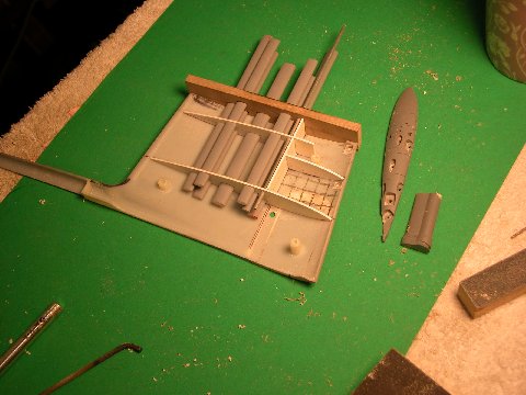
Sail detailing masters
This is how far I got with the retractable masts and bridge and lower platform masters before being informed that this work, if it were turned into tooling and kit parts would radically increase the price of the kit. So, this work sits in a box awaiting the day I have time to produce aftermarket sail mast, scope, antenna, and sail interior detailing kits. If no interest materializes, then this stuff will join two shed fulls of similar crap for my estate executor to haul to the local land-fill. (I don’t like to think about it.)
I don’t know what the hell happened in China with the propeller, but, the mockup they sent was horrible! No good reason for it: I sent them a 1/96 sample of the SKIPJACK wheel for scanning. What happened?! Anyway… after examination and rejection (at considerable velocity, against the far wall) of the mockup propeller, I made up my mind to build a physical 1/72 propeller for them to scan. It being my hope that they would produce a CAD file off the new propeller from which to eventually drive a CNC machine for tool fabrication.
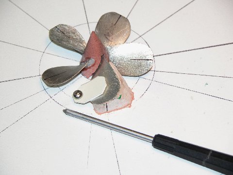
Propeller correction master in construction jig
Here’s the build-up of that propeller master. It’s my practice to make one propeller blade master; pull a high-temperature RTV tool from that; cast up the required number of blades; then assemble those blades about a RenShape hub mounted on a blade assembly jig, securing them with CA mixed with baking soda. Me much smart!
The amount of corrective work required on the hull necessitated creation of this securing/layout fixture.
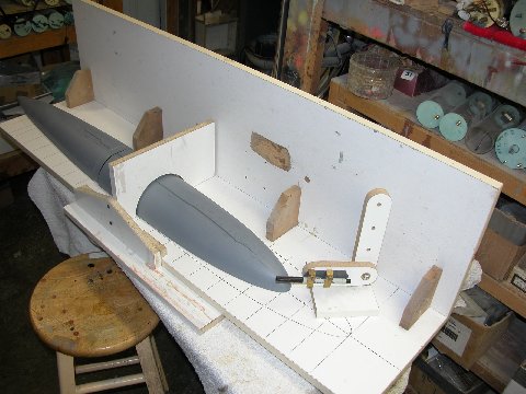
Securing/Layout fixture with 3D mockup in place
It would permit me to accurately lay down radial lines, longitudinal lines, and to loft – directly off a scale drawing of the SKIPJACK – engraved line locations. The pen loaded surface-gauge, running along the vertical, longitudinally running board, marks off longitudinal lines. The surface gauge mounted to the transverse vertical board lays down radial lines – such as the station/ section lines spaced evenly along the length of the hull. Proper layout is everything in model making – if you don’t establish and follow your datum points, lines, and landmarks, you will never achieve reasonable symmetry. (Sounds like something Buddha would have said.)
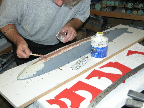
Applying 2-part filler to correct upper contour
Here is the securing/layout fixture partially disassembled to better access the mockup for re-contouring. Note the cardboard station templates in the foreground – used to check my work as I re-established the correct radius to the erroneously flat portions of the mockup. I lay down some filler, let it cure, then worked it, a bit at a time, with a course file, constantly checking the contour with the templates.
The only non-round portions of the SKIPJACK hull are two deck flats, one ahead, and one astern of the sail – flat to give assured footing to line-handlers and other men on deck.
Aluminum ‘flats’ screwed to mockup prior to applying filler
I elected to first get the entire upper hull back to round with filler (no corrective actions required to the lower hull), and only then to build up the flats. The two flats were re-established by screwing down suitably shaped .030″ thick aluminum deck flat forms upon the hull and building up filler between the hull and form edges. See the long lines either side of the sail on the drawing taped to the vertical, longitudinally running board? Those lines simply identify the anti-skid outline. However, I failed to inform the Chinese of that and they interpreted the lines to denote a flat, so that’s how the mockup hull came out, one long flat to the deck, not two smaller ones. My mistake – not properly explaining this feature in the cover letter that accompanied the documentation I sent – cost Moebius both time and money. Lesson learned!
Note how I used different colored hardener in the filler mix to identify high and low points as I applied and filed back the filler as I restored the upper hull back to a round section.
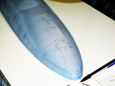
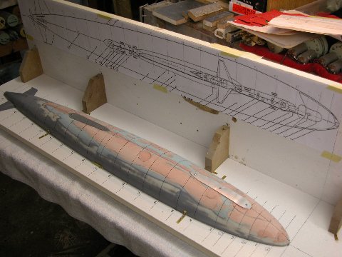
Penciling in the engraving marks to restore lost detail
Before I could scribe in all the detail lost when I re-built the top of the upper hull, I had to first lay out, in pen and pencil, the position and shape of the eventual engraved lines. The securing/layout fixture made that chore a quick and accurate one. You can make out the forward flat very well in this shot.
After layout, I scribed in all the lines lost during the hull re-build. Some of the engraving to be performed represents the upper sonar dome window, upper torpedo tube shutter-doors, forward escape buoy, escape trunk hatch, torpedo loading hatch, reversible cleats, salvage plates, capstan head, etc.
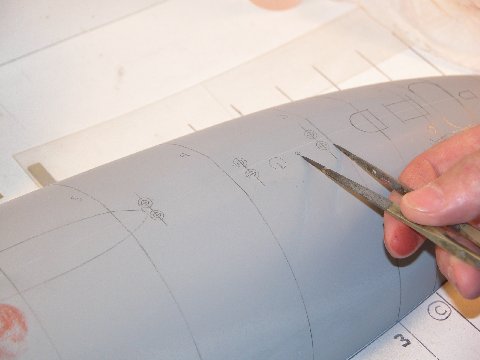
Transferring landmark points to model in prep for engraving
I also failed to provide the Chinese with any information that identified the point of rotation of the full-flying control surfaces. So, they took their best guess as to center-of-rotation for each control surface … and got each and every one wrong. Not a big deal to static kit-assemblers, but for those who would go on to assemble the kit for R/C operation, control surface center-of-rotation position is a vital consideration both for scale looks and flutter avoidance.
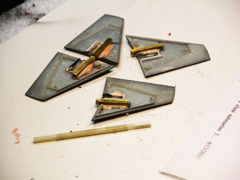
Re-engineering control surface pivots for practical (and accuracy) considerations
So, I modified the mockup control surfaces with properly located foundations to accept the control surface operating shafts. I should have been on top of this from the beginning of the project, but missed it. Bad.
Finally, I got all the fixes I could identify incorporated into the Chinese mockup. Here it’s been test fit together, ready for shipment to Moebius who got it just in time to make the Chicago IHobby show last year. At this first public showing of the Moebius Models 1/72 SKIPJACK, it was well received.
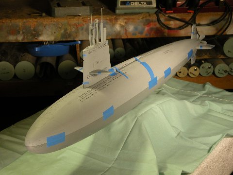
Corrected 3D mockup test fitting – looks good!
After the show, the corrected mockup was shipped to China for laser scanning, which produced a file suitable for CNC cutting of the production tools. The writing you see on the mockup (looks like tiny vents here) is there to identify the corrected areas, just to make sure my changes would be identified and the re-contoured areas recorded into the software.
Shots of the mockup at the IHobby show can be viewed along with comments at:
Trackbacks: