
Report to the Cabal: Part 7
Bonding the Sail and Hull, Installing the Sail Linkage, and Attaching the Radial Flanges
Now we’re on a roll: actual bonding of the major sub-assemblies into proper hull halves, assembled sail, and establishment of the means of securing the two hull halves so that access to its interior is assured and easy. From this point, to improve the clarity of the discussion, I’m going to refer to the fittings kit parts by both the noun-name and letter identifier pictured in Part-4 of this Cabal Report.
Hull quarter assembly is a departure from what the kit supplied instructions advocate. Remember, the kit, as packaged, is intended to be assembled by average hobbyist into a seamless, non-functioning, static display model. However, as an R/C submarine, we need access to both the hull and sails interiors; we have to take measures that permits access those spaces. So, what I describe below is the creation of upper and lower hull assemblies that can be opened up to access the interior of the hull, and the devices mounted on the hull but contained within the sail.
Gluing bottom hull halves together using flat surface
Access to the interior of the hull is through the horizontally split upper and lower halves. At the stern and bow the longitudinal break transitions to a radial break at the lower bow and upper stern. The radial flange forward draws the hull halves together forward, and a single machine screw, running through the after radial flange, compresses the hull halves at the stern.

Using assembled (and cured) bottom to ‘key’ upper half assembly
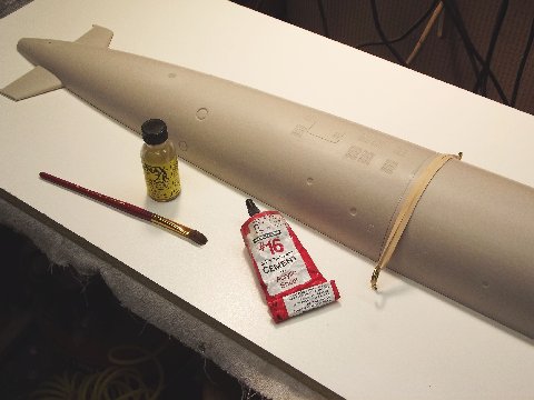
The forward and after lower hull quarters are welded together using solvent type cement. As you can see, the two hull quarters are mounted on a flat board to insure that their edges fall along the same plane. Note that a rubber band is used to push the after end of the forward quarter down hard onto the radial flange of the after quarter. Just as in metal welding, which involves pre-heating of the weld area, the contact areas of the plastic to be bonded is treated to make it receptive to deep fusion once the state change is effected to the parts being joined. Before assembly, the radial flange of the lower after quarter and mating surface of the forward lower quarter are soaked in the very thin solvent cement to soften those surfaces. Then, quickly, the gelled solvent cement is beaded onto the flange and the two hull quarters assembled on the flat board, the rubber band made up, and the work left for twelve-hours to harden.
Once the center, radial union between the two lower hull quarters has hardened, the assembled lower hull is taken off the board, inverted, and the two upper hull quarters are set upon it – a test dry-fit. Any sprue left at the equatorial separation line between the lower hull and two upper hull quarts is identified and cut and filed back till a tight fit between the three hull pieces is achieved.
Take things apart, insert two slivers of wax-paper onto the edge of the lower hull over the radial joint – this to prevent any adhesive that runs down from the upper hull pieces from getting onto the lower hull piece. Don’t worry, if you keep the wax-paper slivers small enough they will conform to the tongue-in-groove union enough so as to not distort the fit between the three hull pieces too much. Or, you can wax the edges. Your call.
Lay the after upper hull quarter down, get it to register with the lower hull and hold the assembly together with rubber bands. Soften the flange of that piece and corresponding inside surface of the forward upper hull quarter with brushed on thin solvent cement, then smear on beads of gelled cement to the surface of the flange and quickly position the forward upper hull quarter atop the lower hull and make the assembly fast with rubber bands. Leave the upper hull to dry twelve-hours.
The reason I’m so specific as to how you assemble the hull quarters is this: As the R/C SKIPJACK features a hull that opens up at its centerline equatorially, it’s vital that the upper and lower hull index together as well as possible owing to the fact that the only clamping force applied when they are assembled is at the extreme bow and extreme stern. Any misalignment between the two hull halves during assembly of the quarters, and you would suffer unsightly open seams between the halves.
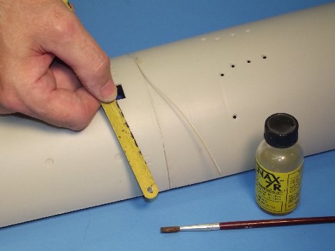
Applying stretched ‘sprue’ filler rod to hull seam (cleaned out with hacksaw blade)

Making the Z-union cuts to the hull halves (stern from upper, bow cut from lower)
As in metal welding, filler rod is sometimes employed when welding large plastic parts together, this to achieve like material build-up and to bridge significant gaps between the two items being fused. Here, a length of sprue (liberated from the SKIPJACK kit), has been heat-stretched to a mean diameter of .025″. This polystyrene rod used to fill the inevitable seam between the two hull quarters of the upper and lower hull pieces. To carry the metal welding analogy a bit further as I explain what we’re doing here: As pre-heating of metal parts to be joined is done to enhance fusion, wetting the groove between the hull quarters liberally with thin solvent cement works to soften the plastic which encourages the polystyrene molecules to interlink with those of the adjoining filler rod and hull quarter. (Unlike adhesive bonding, we’re welding the parts and filler rod into a whole. Once the operation is complete, no bonding agents are left, only a fused together assembly of identical material – in this case, polystyrene plastic. The strongest possible union of separate parts). If need be – to insure an open seam of uniform width and depth to better receive the filler rod – use an eighteen-tooth-per-inch hack-saw blade to achieve a uniform .025″ wide by .025″ deep groove for the filler rod. Lay in the filler rod, brushing on solvent as you go. Things get gummy as you work and soon the rod dissolves into the adjoining material. The result is a near perfect fusion weld between the forward and after hull quarters. This is going to be an R/C model submarine … we’re not screwing around here! Strength and avoidance of dissimilar substrates are vital considerations during assembly.
Carefully following the inked on radial lines, a razor saw was used to remove the tail-cone from the after upper hull quarter, and bow from the forward lower hull quarter. Using a wide hard-block, sand the radial faces of all parts with #240 sandpaper. If you were careful you lost no more than 1/16″ of kerf, that will be made up later with CA-baking soda filler.
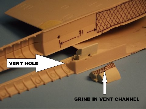
Placement of the diesel exhaust fairing vents
When the R/C SKIPJACK leaves the surface, an unobstructed path for venting air, trapped in the diesel exhaust fairing, has to be provided. Failure to get all the air out of the fairing will upset the boats trim and make it difficult to hold exact depth when cruising along at slow speed. So, the following operation has to be done before securing the sail foundation pieces (sail-to-hull mounting foundations-R) to one half of the sail assembly: Grind a 1/8″ deep by 1/8″ wide vent channel atop the after foundation piece. A corresponding vent hole is drilled into the top, forward bulkhead where the exhaust fairing meets the trailing edge of the sail proper.
You will need the ability to flex the bottom of the sail a bit to get the lower sail plane bell-crank (sail plane bell-crank-T) on and off its bell-crank shaft retainers (sail plane bell-crank shaft retainers-S). To accomplish that the sail foundations are glued to only one side of the assembled sail. This permits the unglued underside of the sail to pull away from the other sail half when flexed to install or remove the lower sail plane bell-crank.
You see here how the sail plane operating shafts fit within the rather thick hub of the resin upper bell-crank (sail planes and bell-crank-Q). The gear portion of the upper bell-crank engages the gear portion of the lower bell-crank which works around its shaft to rotate the upper bell-crank when subject to the axial motion of the pushrod that runs from the motor-bulkhead of the SD.
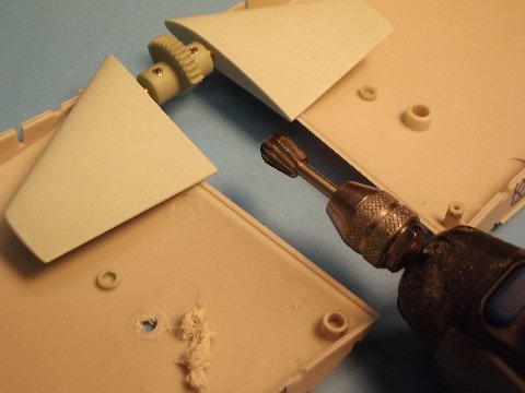
Modifying the sail plane pivot holes to accommodate control shaft/crank
Here I’m grinding away the raised, molded bores of the original operating shaft holes projecting from inside the sail halves. The hole, as it is, is too big for the 1/8″ diameter sail plane operating shaft. You see between the trailing edge of the sail planes and the ground away bore of one sail half the as of yet untouched bore. A small resin bushing (sail plane operating shaft bushings-N), installed into the original hole reduces its diameter to the required 1/8″ bore required by the sail plane operating shaft. The two bushings are pushed in and CA’ed in place. Note that a set screw, set within the hub of the upper bell-crank unit, secures the operating shaft of a sail plane – these set screws easily reached from the opening in the bottom of the sail assembly.
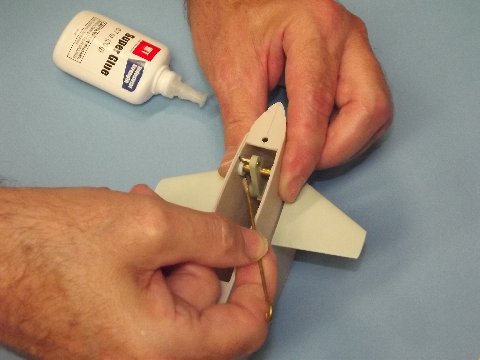
Critical placement & securing of the lower crank retainers inside sail
Tape the halve of the sail together. install the sail planes by running each operating shaft into the bore of the upper bell-crank. With the two sail planes lined up parallel to the top of the sail, and the center of the gear section facing down and perpendicular to the planes, tighten the two set-screws to secure the planes to the upper bell-crank part.
The two resin lower bell-crank shaft retainers are placed on the ends of the brass pivot pin, and the entire unit installed into the inverted sail and oriented so that its teeth meshed with those of the upper bell-crank. Squeezing the hull halve together between thumb and forefinger, to hold the shaft from moving, tack-glued the retainers to the sail halves – use only enough CA to hold them in place. Check that rotation of the lower bell-crank caused free unbinding rotation of the upper bell-crank. Break and reposition the retainers as required until free, minimal back-lash operation of the linkage is achieved.

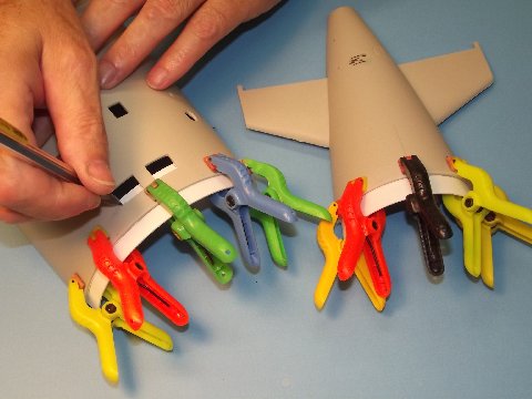
Example of glue technique on a taped assembly (note removed planes)
Position the clear piece that represents the emergency stern-light within the sail, then assemble the sail and hold it together with masking tape. Avoiding those areas where masking tape is (you don’t want the thin glue to get sucked into the tapes edges by capillary action), brush thin solvent cement along the seam at the leading edge of the sail, along the top of the sail where the sail top piece will sit, along the trailing edge of the sail, and over the seam atop the diesel exhaust fairing. Also run cement onto these seams from the inside. Leave the assembly to dry for a few hours. DO NOT apply cohesive glue to the bottom seam of the sail assembly. Remember, you want to flex the bottom portion to get the lower bell-crank shaft in and out of its resin retainers.
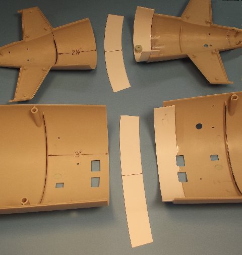
Illustration of Z-union flange assembly
Clamping glued flanges; note vent hole overlap of lower flange
To the right are installed flanges. Center and left are yet to be installed flanges and the hull sections they go into. you want one-half of the tail-cone flange (after radial flange-V) to project past the radial edge. However, you want only 3/8″ of the forward flange (forward radial flange-W) to project past the bow pieces radial edge. As they arrive, the stiff, polystyrene flanges are flat. You can easily put a curl into them by running a flange piece over a small dowel as you apply pressure between dowel and finger as you pull the flange through. Keep at it until the flange retains a curl close to the radius of the part it will fit within. Test fit the flanges to the tail-cone and bow piece. Onto the bow piece flange mark with pen or pencil where some of the flange overlaps two of the flood-drain openings. Once you’ve affirmed a good fit of the flanges, remove them, cut away those areas of the forward flange so marked, coat the flange and hull pieces with thin solvent cement to soften they’re surfaces, apply gelled cement, then quickly assemble the flanges to their respective hull pieces, clamp and let sit for at least twelve-hours.
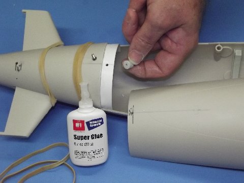
Z-union securing screw and flange foundation piece
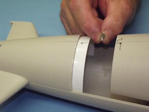
Beauty of the Z-union – one screw holds it all together!
Time to work out the means by which the upper hull will be made fast to the lower hull. Rubber-band the removed tail-cone to the lower hull. Place the upper hull onto the lower hull, insuring that the indexing pins and long horizontal edges of the two hull halves fully engage – leave the sawed off lower bow piece off-model during this operation. Rubber-band the two hull halves to they don’t lift up on you. On the upper hull, 1/4″ forward of the after radial edge, on centerline, mark off and drill a 7/64″ hole that will pass the 4-40 securing screw – drill through both the upper hull and after radial flange.
Remove the upper hull. Soap the threads of the screw (to keep adhesive from sticking), insert the screw thread through the flange hole; hold the foundation under the flange hole (upper hull securing screw and foundation-X) and run the screw into the tapped hole of the foundation and tighten till the foundation is pressed tight against the bottom of the flange; apply some CA between the foundation and flange – not too much!. Spritz on some zip-kicker to cure the glue; unscrew the fastener; with a counter-sink bit bevel the hole in the upper hull so that the screws head sits flush.
A single 4-40 flat-head machine screw passes through a hole in the upper hull half, pushing it all down upon the after radial flange. Up forward, the radial flange of the lower hull captures the bow piece attached to the upper hull, pulling the two hull halves together there. The Sharpe-kachur Z union at work!
Trackbacks: